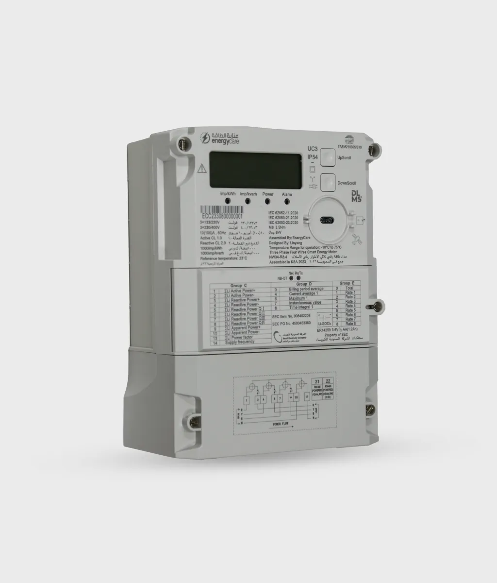
ELEGANT DESIGN
Our smart energy meter features an elegant and modern design that blends functionality with style. Its sleek form factor, intuitive display, and compact build make it easy to install in any environment—from homes to commercial spaces. The ergonomic layout ensures effortless operation, while the premium finish reflects innovation and sophistication.
POWER SMARTER
Energy care smart energy meters embody our commitment to advanced data-driven energy management. Our smart electricity meters integrate state-of-the-art metering infrastructure (AMI) with real-time analytics and intelligent communication systems. Designed for precision and reliability, they enable accurate energy measurement, two-way data exchange, and support efficient load management and improved grid stability.
DATA ANALYTICS
Our smart energy meters don’t just record electricity usage—they analyse and interpret data to create valuable insights. Through advanced analytics, every watt becomes a key to smarter, more efficient energy management. With smart analytics, energy meters become intelligent partners, enabling smarter energy decisions.
FUTURE PROOF
Our future-proof smart energy meter ensures long-term reliability and adaptability to upcoming technologies and regulations. It integrates hardware and software flexibility to support future advancements in smart grids communication networks. The DLMS protocol allows it to be upgraded in-site thus future-proofing your smart energy investments.
Technical Specification
| Sr. No | Description | Unit | Technical Parameters | |
|---|---|---|---|---|
| DC (whole current) | CT connected (Transformer operated) | |||
| 1 | General Information | |||
| Model Number | NW34-R8.4/NW34160A-R8.4 | NC34-R9.5 | ||
| 1 | General Information | |||
| Model Number | NW34-R8.4/NW34160A-R8.4 | NC34-R9.5 | ||
| Service Type | 3-Phase, 4-Wire | |||
| 2 | Ratings | |||
| Nominal Voltage (Un) | V | 3×133/230/400 (Max endurable 500V per phase) | ||
| Operating range | V | 0.8 Un ~ 1.15 Un | ||
| Nominal Frequency (fn) | Hz | 60 | ||
| Nominal Current (In) | A | 10/20 | 1.5 | |
| Maximum Current (Imax) | A | 100/160 | 6 | |
| Minimum Current (Imin) | A | 0.5 | 0.015 | |
| Transitional Current (Itr) | A | 1 | 0.15 | |
| Starting Current (Ist) | A | Active (Cos Φ): 0.004Ib; Reactive (Sin Φ): 0.005Ib | Active (Cos Φ): 0.001Ib; Reactive (Sin Φ): 0.003Ib | |
| 3 | Accuracy | |||
| Active Energy | 1.0 | 0.5S | ||
| Reactive Energy | 2.0 | 2.0 | ||
| 4 | Power Consumption | |||
| Voltage circuit | 1.65W/3.5VA | 1.65W/3.5VA | ||
| Voltage circuit (With communication module – Idle) | 2.06W/4VA | 2.06W/4VA | ||
| Voltage circuit (With communication module – communication in progress) | 2.15W/4.5VA | 2.15W/4.5VA | ||
| Current circuit | ≤ 0.4VA | ≤ 0.4VA | ||
| 5 | Meter Constant | |||
| Active Constant | imp/kWh | 1000 | 10000 | |
| Reactive Constant | imp/kvarh | 1000 | 10000 | |
| 6 | Pulse Indicator | LED w/ wavelength 610-700nm | ||
| 7 | Protection | |||
| Protective Class for insulation | II | |||
| Rated Impulse Voltage (Uimp) | kV | 8 | ||
| Protection Degree | IP54 | |||
| 8 | Temperature | |||
| Limit Range for operation | °C | -10 ~ + 75 | ||
| Limit range for storage and transport | °C | -10 ~ + 85 | ||
| 9 | Relative Humidity | RH | ≤ %95 (no-condensing) | |
| 10 | Display | |||
| Display method | Segment Type | |||
| Connection | Pin | |||
| Dimension WxH | mm | 75 x 22 | ||
| Character Height | mm | 8.32 | ||
| No. of digits | 8 | |||
| 11 | Life time | |||
| Number of Batteries | Nos | 2 (One internal + One replaceable) | ||
| Storage life of Battery | Years | ≥ 15 | ||
| Operating life of Battery | Years | ≥ 1 (RTC keeps active when mains power off) | ||
| Meter life time | Years | ≥ 15 | ||
| 12 | Terminal type and hole size | mm | Screw type 9 mm (For cable accommodation) | Screw type 5.3 mm (for cable accommodation) |
| 13 | Outline Dimensions | mm | 231 (H) x 173.5 (W) x 93 (D) | |
| 14 | Weight | Kg | 2.0 | <1.5 |
| 15 | Sealing arrangement | Pcs | Ultrasonically welded and 4 one-way screws on casing, Modem/Battery Cover (1) Terminal Cover (2) (by utility) | |
| 16 | Casing and Terminals material and characteristics | |||
| Meter Base | PC + %10 GF | |||
| Meter Cover | PC + %10 GF | |||
| Terminal Block | PBT + %30 GF | |||
| Terminal Cover | PC + %10 GF | |||
| Terminals | H59 Copper, Tin Plated | |||
| Terminal Screws | Grade A stainless, Tin plated (>5microns) | |||
| Terminal Screw head Type | Hexagon socket head (M8) | Phoenix head (Star) | ||
| 17 | Control Switch Method | |||
| Method | Supply Control Switch (SCS) | Load Control Switch (LCS) 160A & CT | ||
| Qty | Nos | 03 (Each per Phase) | 01 | |
| Utilization Category | UC3 | NA | ||
| Rated Operational Voltage | V | 230 | 250V | |
| Rated Frequency | Hz | 60 | ||
| Operational Current | A | 120 | 1 | |
| Electrical Endurance | Nos | 5500 ON/ 5500 OFF | ||
Reviews
There are no reviews yet.